News
CuPID at the GEM Conference! (E. Atz, Jul. 11, 2019)
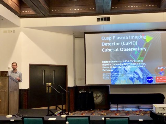
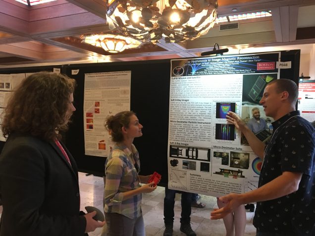
Recently, at the end of June, the CuPID team from BU presented at the Geospace Environment Modeling (GEM) conference in Santa Fe, NM. Our Principal Investigator Brian Walsh presented the mission to a conference session focusing on magnetic reconnection. PhD student Emil Atz presented the CuPID instruments during an evening poster session and won the poster competition for the research area!
Overall, the conference was a great success with plenty of science, learning, collaboration and fun! Special thanks to the organizers and the NSF for another great GEM Conference!
It is a Flight-Unit CubeSat! (E. Atz, Feb. 2, 2019)
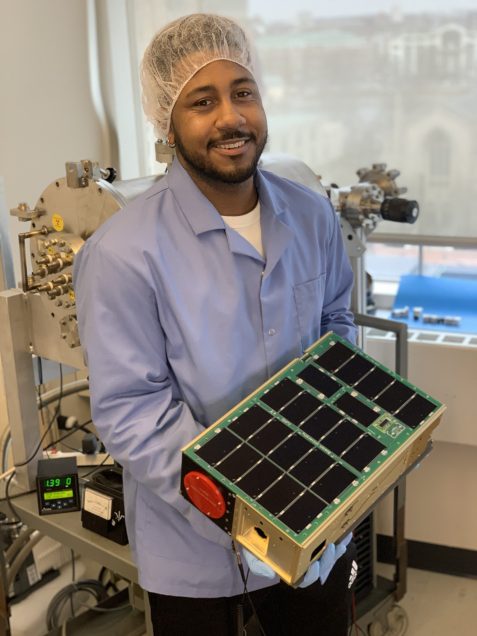
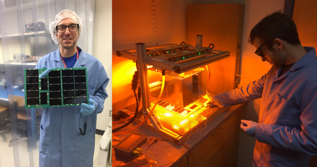
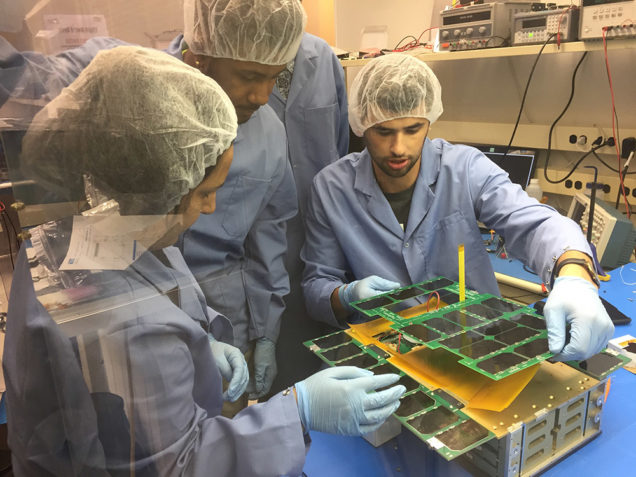
This week, the CuPID team finalized the chassis structure, and began to test how components would integrate onto and into the chassis. At Boston University, we tested the solar panels on the chassis, both in fitment and performance. Below, Thompson Cragwell, an engineer in our research group proudly holds our flight CuPID chassis and largest flight solar panel.
In Maryland, at Planetary Systems Corporation, CuPID was inserted into their Canisterized Satellite Dispenser (CSD), which will be used to eject the satellite from the rocket after reaching orbit. Check out the video below of catching the satellite as it is shot out!
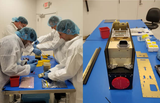
At our collaborators, Adcole Maryland Aerospace, we tested the fitment of their avionics components in the chassis. The avionics, dosimeter, GPS antenna, and radio antenna fit beautifully into their designed spaces. Next step: Final integration and testing!!!!
More Power! (E. Atz, Dec. 11, 2018)
In the last two months, we have built and began testing the flight model solar panels for CuPID. If you remember, we posted about building the small, -X face solar panel in May, yet this panel was only able to fit 7 solar cells. Using the lessons learned from manufacturing the -X panel, we made the two main power producing panels for CuPID. Together, these two panels are enough to power the satellite with their total 33 solar cells! Below, Aleks and Emil lay a string of cells down onto the double sided Kapton tape adhered on the flight FR4 circuit boards.
Solar panels are a crucial part of a satellite, so testing needs to be rigorous. We test our solar panels electrical power production under a simulated sun environment, as well as exposing the panels to deep vacuum and thermal cycles like they will experience in orbit.
Ready for First Contact! (T. Cragwell, Oct 22, 2018)
September 27th and 28th: Kevin Jackson and Steven Erickson of Flexitech Aerospace came to Boston to perform the installation of a custom ground station. The ground station will communicate with CuPID once in orbit. The ground station consists of two major components, the main computer terminal and the radio antenna. There were quite a few components so it took the combined effort of the whole team to properly set it up!
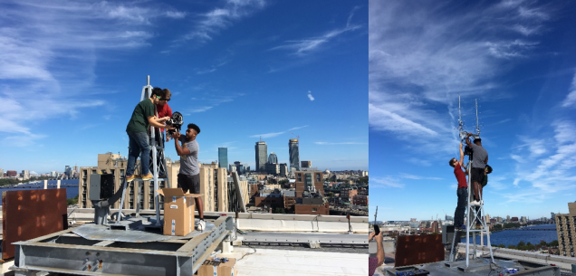
The radio antenna tracks a satellites orbit path using occasional location information given by the satellite that is then used to predict the future location and time of ground station contact passes. The antenna then sends information from the satellite down to the ground station located just below the antenna. The actual motion of the antenna is driven by a motor located inside of a large black header, which turned out to be quite heavy!
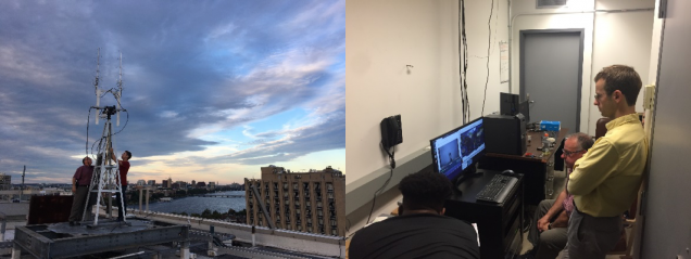
After two days of some serious heavy lifting, epoxying, cable routing and teamwork were wound up with a well-functioning ground station. Below is a time-lapse video of the antenna tracking the ISS overhead!
*This post was written by Thompson Cragwell, posted by Emil Atz.
Successful Vibe Test (B. Walsh, May 26, 2018)
CuPID goes through a successful vibe test! The violent shaking of a rocket during launch can cause a number of issues with a spacecraft including parts rattling loose, electronics being damaged, and optics being offset in an imaging system.
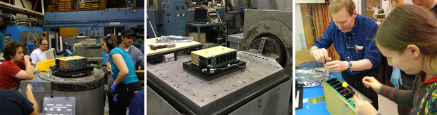
To test the spacecraft and instruments prior to full integration, CuPID went through a risk reduction vibrational test in early May. The test shook the spacecraft at similar frequencies and intensities as expected from the rocket. All systems passed the test successfully. The video below shows part of a vibrational test on one axis.
Power Up! Solar Panel Build (E. Atz, May 15, 2018)
A few weeks ago, Aleks Zosuls and I populated cells on a printed circuit board (PCB) for one of CuPID’s solar panels. It was decided to affix the solar cells to CuPID’s solar panel PCBs using double sided Kapton tape. Kapton is a thermal and electrical insulator, and with adhesive on both sides, it makes for a very robust method to affix two flat components together. The tricky part about this assembly is that the string of 6 cells needs laid down all at once, since they need to be soldered together on the side that attaches to the PCB.
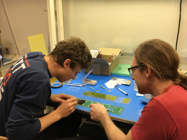
Prior to building a functional solar panel using real cells, we worked out a specific assembly process using parts laser cut from a thin acrylic sheet as a model to test out assembly procedures. We ended up building two of these model solar panel boards.
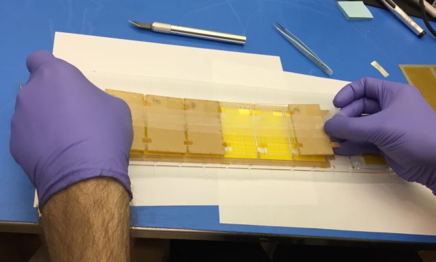
Getting 6 cells to line up perfectly onto a surface that will permanently attach them requires some specific equipment. We made special jigs and guides cut out of the acrylic sheet with a laser cutter to help align the components as they were assembled.
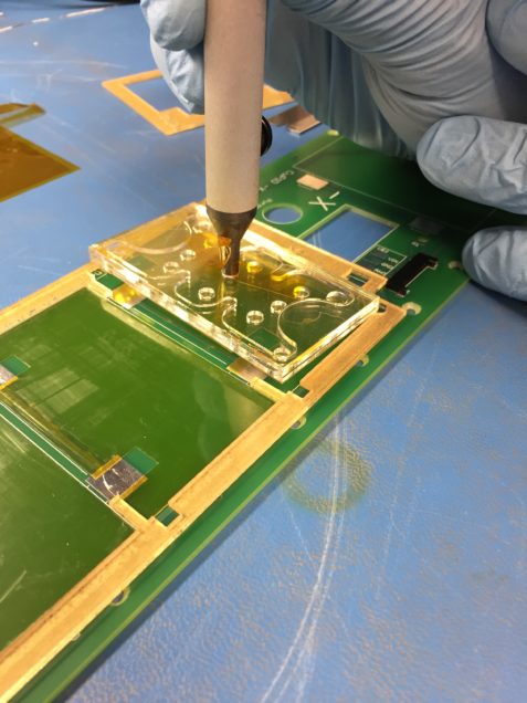
We also made some special tools to help us with the assembly. The double sided Kapton was cut to the proper pattern with the same laser cutter, but because it is 0.005 inches thick, it was rather hard to handle and align by hand. We made a tool to attach to a vacuum pen, which held the Kapton tape by the top release layer, so we could place it down through the jig onto the PCB (the Kapton has a plastic layer over one of the two sticky sides that you peel off).
In the end, we came out with a functional solar panel for CuPID that is soon to be tested and characterized. Check out the time lapse video below and watch the 3 hour build in just 5 and a half minutes!
Why Space Parts are Different than Earth Parts (E. Atz, Jan 15, 2018)
It is pretty common in the satellite field to hear, “that costs how much!?” Generally speaking, space grade parts cost more because of the effort required to minimize the risk of failure. On Earth, an inexpensive part could fail, but could be replaced (with some frustration of course). On orbit, the failure of an inexpensive part could terminate the mission of a spacecraft.
The environment outside of Earth’s atmosphere is not as friendly as it is down here. There are many differences in the environment, creating different results in how a part performs. Below are some notable environmental challenges that space parts, and satellites like CuPID for that matter, must survive in.
Vacuum (not like the kind in your house)
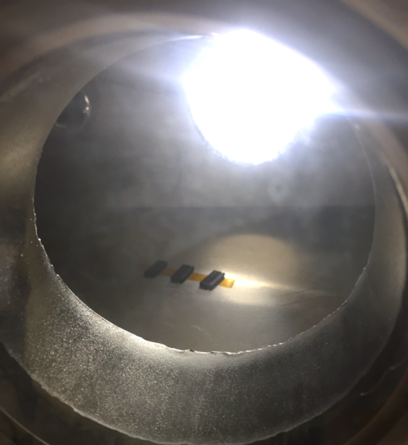
Outside of the Earth’s atmosphere is the so called ‘vacuum of space’. This creates a problem of off-gassing. Materials, when they no longer have an atmosphere keeping trapped gasses inside the material, release these gasses. Sometimes large percentages of the mass of a material can be removed from a part simply by being in a vacuum! CuPID, because of its optical science mission, has strict off-gassing requirements such that any released gasses do not obscure the imaging detector. Off-gassing happens here on Earth too, but to a lesser extent, like the “new car smell”.
The hot side and cold side of Earth
In a particular orbit, a satellite can experience total sun, and total eclipse. When a satellite is between the Earth and the Sun, it heats up, and when in the shadow of Earth, it cools down. CuPID has been designed to live in a temperature environment of -35°C to 70°C (-31°F to 158°F). That is colder than a freezer and hotter than a hot tub! CuPID will orbit Earth once about every hour and a half, meaning the satellite will be in an environment that will change by nearly 2°F every minute!
Radiation, and lots of it
Surrounding the Earth are belts of radiation, called the Van Allen Belts. The Van Allen Belts are a collection of highly charged particles, electrons and ions, that are trapped in the the Earth's magnetic field. Each particle moves around the Earth differently based on where they are and their charge as well as a few other factors. One motion for example is the motion along Earth's magnetic field from the North Pole to the South Pole, which these particles traverse in seconds. Moving at tens of thousands of miles per hour, these particles have the ability to significantly degrade the performance of electrical components such as circuit boards and solar cells as they literally smash into the spacecraft. One example of spacecraft damage is the color change of glass, such as cover glass on a solar cell.
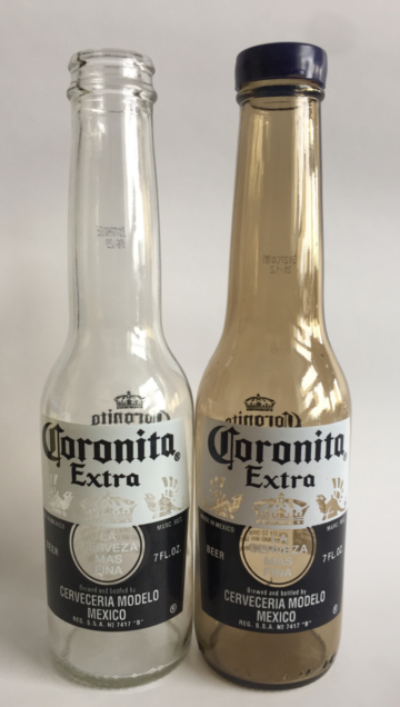
Space is a tough place for a CubeSat, or any satellite or human for that matter. Extensive work goes into building, testing and proving that the space parts that make up the satellite will perform properly when on orbit. Following posts will describe some of the testing done on the parts that make up CuPID.
First Things First: A Design Review Meeting (E. Atz, Sep 8, 2017)
What is a CDR?
In many areas of work, before a large project progresses far from concept into design, fabrication, and testing, an important meeting must be scheduled. In this meeting, team members present progress and future work to colleagues as well as a set of second party reviewers. This type of meeting is called a Critical Design Review, or CDR for short. Commonplace for development of spaceflight hardware, CDR’s are important to a project because they allow issues to be discovered before significant progress on a project has been made. Issues caught in a CDR can prevent extensive re-working of a project.
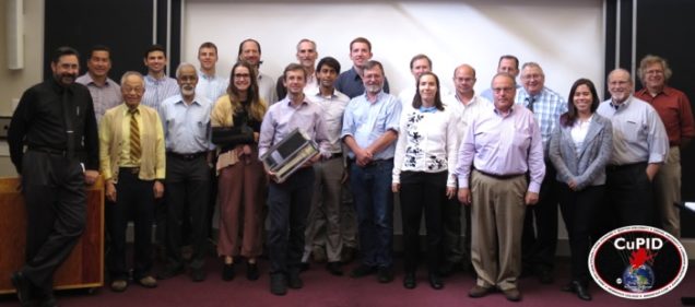
Last week, the CuPID team met at John’s Hopkins University for a CDR with external reviewers from NASA Goddard, Virginia Tech and John’s Hopkins, Applied Physics Lab (APL). In this meeting, team members from the various eight institutions presented their designs of the many subsystems in CuPID. The CuPID CubeSat Observatory is a custom spacecraft with many systems being designed for the first time, many in parallel.
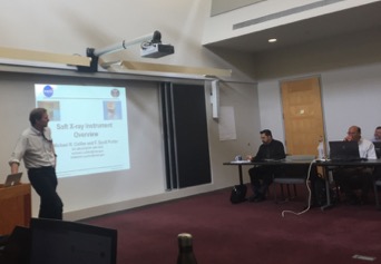
With 8 different organizations contributing to the mission, appropriate communication between people and components is key. The team spent significant time at the CDR going over the plans for interfacing components. A clean interface plan will ensure a part developed by team A can plug into a part developed by team B and all of them put together can run software developed by team C which can them be tested by team D. (…in reality this goes all the way to team H!)
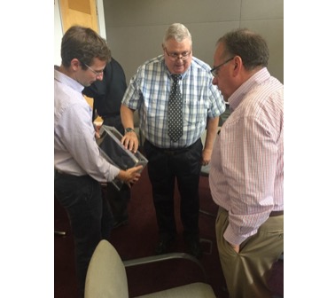
A second area that garnered a lot of discussion was the pointing of the spacecraft. There are a huge number of intertwined variables that impact the best way to point the spacecraft. The spacecraft wants to generate as much power as possible, but it also needs to point the science instrument in a useful direction. At the same time, the star tracker cannot point at the Earth or the sun, and the GPS antenna must be in the appropriate position to obtain positional information. These and many other considerations all fed into the discussion of optimizing the performance of the spacecraft.
Now What?
Though daunting, last week’s CDR showed how well the program has been adapting to the difficulties of cross-team (and cross-state) cooperation. Different teams are spearheading power systems, scientific payload, software, and ADCS/EPS suite, although member groups have collaborated, this full combination of teams has never worked together before as a unit. A playbook of how and when people in the unit would communicate and act did not exist prior to the project.
This reinforces CDR’s importance — to ensure the subsystems are aligned, surface any discrepancies and cross-platform/cross-subsystem integration issues, and agree on a method to communicate future changes.
The team left CDR with a number of important action items that will help bring the satellite closer to its final design. The most notable areas of focus involve the interfacing of subsystems; with 8 entities working on various components, a common-ground is essential so the individual parts can fit/work together in unison.
CubeSats (B. Walsh, Jul 16, 2017)
As the very first post, we’ll look at cube-satellites or cubesats before getting into specifics about the Cupid mission. Very simply, a cubesat is a small spacecraft that fits into several standard sizes. Below shows several different options and a loaf of bread for scale of size.
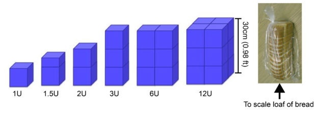
Each “U” in the label above is 10cm x 10cm x 10cm cube. Cupid is a 6U spacecraft.
These agreed upon standards for size and shape of the spacecraft has enabled a flood of space technology and science development over the past decade. Rather than a single rocket ferrying just one spacecraft into orbit, these standards allow a rocket to carry many spacecraft into orbit. This means rather than a single space mission footing the entire bill of the launch, the cost is split over 15 or 20 space missions catching a ride (think splitting a cab with friends or riding in an uber pool). A recent launch out of India carried 104 cubesats with a single rocket!
These developments have greatly reduced the cost of developing a space mission and enabled a new breed of high-risk, high-reward missions. Historically the aerospace industry has been extremely risk-adverse. If someone is spending hundreds of millions of dollars and up to a decade developing a single spacecraft, he or she understandably doesn’t want to inherit much risk of failure. Unfortunately this isn’t the best behavior for innovation and growth. As with any area of life, trial and error is one of the best ways to learn. With a cubesat costing just a few percent of a typical large-scale spacecraft, one can afford to take on higher risk. These higher-risk, high-reward projects have provided the much needed test bed for innovation.
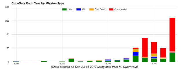
Cubesats were first developed in the early 2000s as tools for universities to teach aerospace engineering. Since this time they’ve rapidly grown in popularity as well as application. The plot below shows the number of launches per year with the color showing the type of organization. Although universities where the pathfinders, commercial spacecraft are now dominating the launch manifests.
More information on cubesat missions can be found at Michael Swartwout's website. Some of my personal favorites are flights which have served as inaugural trips into space for countries such as Ecuador (NEE-01 Pegaso, 2013), Estonia (ESTCube-1, 2013), Uruguay (Antelsat, 2014), and Switzerland (SwissCube-1, 2009).